A New Design for a Side Bender
This side bender is based on three key ideas:
- all the bendings are performed on convex surfaces,
- the wood is inside a couple of tensioned slats and
- that tension doesn’t work against the operator thanks to an ingenious mechanism.
For small guitarmakers, bending the sides of a guitar, regardless the method, is a job that can be anything between easy as pie or become a nightmare. There are two main systems: bending irons (electric, gas or even charcoal heated) and mechanical presses. Among the latter, the Fox Bender is an ingenious, proven device designed by Charles Fox and found all around the world especially in small shops. It worked well for me doing the waist bends, but after some bad experiences with cutaways in curly maple I decided to use it exclusively for the waist. Part of the problems were mine, I guess, because I made my machine without plans and using my own screws, springs, etc. Whatever the reason, I went back to my humble bending iron; I could get decent results with it, but they took much longer than I thought reasonable.
I established a set of requisites for the new machine:
- It should bend only convex surfaces. That way, the area being bent is always in contact with the form.
- It must not be the machine that determines how long the wood will stay cooking inside (this will be explained below)
- Removing the sides must be easy and fast.
- A single machine should bend several different guitar models without having to disassemble it completely. Every new model should be easily translated into machine hardware.
- One operator must be enough to handle the machine.
- It must not be much more complex, difficult to make or expensive than the Fox Bender.
I went through innumerable designs, some quite complex, discarding them for different reasons.
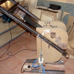
This is how the last version looks:
It won’t be the last one; I have some improvements pending, but the working principles described here won’t change.
The requisites in the previous list were all met, some with more success than others:
- Fulfilling the first requisite was not difficult. A concave surface is convex when seen from the other side. The bending must proceed in several stages, using convex removable forms (explained later).
- I found the second requisite extremely difficult. My initial designs were faulty mostly due to the number of clamps used for pressing the wood against the forms as it was being bent. They were so slow to set up that the wood was burned when the bending was complete. Tensioned slats don’t require clamps for pressing the wood against the forms, so I thought of using them very early in the design. Unfortunately I discarded them all the time until I thought of a mechanism that, in fact, is the brightest idea in the machine. With it, the slats are pulled tangentially from the edge of the instrument along its entire perimeter.
- Removing the sides is not as easy as I would have wanted. While it is not a problem in itself, it lacks the elegance of the other operations. I have some ideas on how to improve this aspect, but haven’t tried them yet.
- The machine can be set to bend different guitar models, but this has limitations. Every guitar model needs a set of inner and outer bending blocks. We will see what they are later; suffice to say that making them is not easy. Switching from a model to another is not easy either, so I would say that the versatility of the machine is its weakest feature.
- Operating this machine is easy enough for one person.
- While the machine is not as easy to make as others, it isn’t out of the reach of small guitarmakers.
Working Principles
The machine is based on three main principles: Convex Removable Forms, Tensioned Slats and Tangential Pull.
Convex Removable Forms
Guitar sides have both concave and convex surfaces. Seen from the outside, the waist, for example, is concave, but that changes if seen from the inside. We will divide the guitar contour into a series of curves, limited by those points where the curvature changes from concave to convex. We’ll build a set of convex blocks (from now on, “inner blocks”), one for each curve. These will be the forms on which the bending will take place, and they will be removable. The bending process will begin with one single inner block present, the one that corresponds to the lower bout. As each curved surface is bent, the next inner block must be fixed in position. Don’t worry if you don’t understand this now; it will be explained below.
Tensioned Slats
These take advantage of several bending mechanics results:
- The bending stress must be limited to a very small area. Simply put: pushing the piece far from the area being bent will put stress on undesired places. It will also put more stress on the point of contact of the form and the wood, but possibly not enough on its vicinity. The result will be an excessive bending of the line in contact with the form, that will separate from it, probably leading to breakage.
- There is an added benefit pushing the outside of the bending, for example with a strap. Beam theory gives us the reasoning behind that. Wood does not support much elongation without breaking, so most of the deformation must come from compression: the strap being part of the beam, it takes the stress on the tension side of the bend. Notice also that the separation that we mentioned above won’t happen, as long as the tension on the strap is enough.
- There is another beneficial side effect of using a strap. With it, cupping can be avoided. Flatsawn wood is not the only one that cups: If you have ever bent tight curves in plastic bindings, you’ll know that cupping due to bending is possible even in uniform materials. For this it is enough to have a slat above the wood and push the assemblage on a convex form, slat outside. However, as the machine can bend both concave and convex shapes (although they are all treated as convex, as explained), it will use a slat to each side of the wood.
Tangential Pull
Highly tensioned slats are the basis of the amazing bending machines that are shown on Bob Taylor’s “Factory Fridays” videos. I was mesmerized every time that I watched them, but trying to reproduce their principles always led me to machines not adequate for a small shop. Pushing a tensioned slat against a form is a difficult task, requiring a huge effort. Taylor was using a motorized design, but that seemed to be beyond my capabilities. And, worst of all, if I still managed to solve that, I foresaw similar but more difficult problems in the cutaway area. The Tangential Pull mechanism avoids all that.
Abstract Description
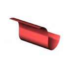
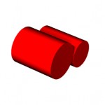
The machine is not very easy to explain, so I have drawn some schematic diagrams. Suppose that the target surface is the one depicted here:
This figure represents a set of two inner blocks that can be used to bend it, following the “Convex Removable Forms” principle explained above.
The following figure represents a machine ready to start bending that shape:
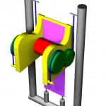
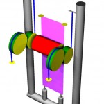
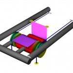
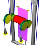
The chassis (the stationary part of the machine) is represented in yellow. There is a piece, which we will call the “bridge”, colored grey. It has two pneumatic cylinders below, pulling an end of the slat/heater/wood/slat layered arrangement (purple) that we will call the “sandwich”, the other end of which is attached to the chassis. This has the already known detachable blocks (in red), but this figure represents only one, as the other has not been placed yet (the figure above this one shows both). Notice that there are more blocks (green) located outside the chassis, the same shape and size as the inner blocks (not always, but basically true for this explanation — more on this later) and in line with them. All the blocks, inner and outer, are firmly attached to the chassis, and they can be placed and removed independently. Notice that, although the second inner block is absent, its corresponding outer blocks are present. Finally, there are two wire ropes (blue) that go from a point firm on the chassis to each leg of the bridge, along the perimeter of the outer blocks. You will notice that the bridge is in equilibrium between two tensions on its ends: that exerted by the sandwich and that exerted by the wire ropes. In what follows, for the sake of clarity, we will not draw the chassis. The points or pieces that must be attached to it are identified by a yellow surface, as shown in this figure:
When the cylinders pull the slats, they become tensioned, the same as the blue wires. The tension on the slats is applied tangentially to the area being bent, due to the outer blocks having the same shape and size as the inner blocks. To operate the machine, we will sway the bridge manually, in this case pulling from its bottom side (arrow). The wire ropes will separate gradually from the small outer blocks, and the sandwich will press on the inner block just on the thin area being bent. The first part of the job will be finished when we arrive at the position depicted here:
Notice that the effort to change the position has been light, as the mechanism has been constantly guiding the pull tangentially to the inner/outer blocks. Modifying the size of the outer blocks has a definite effect on that effort. We can take advantage of it to achieve a self-leveling (or almost) bridge, that can balance its own weight, freeing the operator from holding or clamping it between operations. Now look at the wire ropes. They have become unwound from the small outer blocks, having contact only with the other two. Arriving at this position has been smooth, keeping the tension on the sandwich constant. In fact, the initial position is still recoverable if we set the bridge back to where it was. Now it is time to place the second inner block (red) and remove the two outer blocks (green) that were in line with the first inner block:
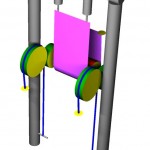
These operations do not require great effort, as neither the wire rope nor the sandwich (both under considerable tension) have contact with the blocks involved. If everything is well designed, these operations can be performed fast as well – a definite advantage when it comes to avoid problems like wood staining, burning or hardening that plague the slower designs. After swaying the bridge again, this time pulling from its top (arrow), we will arrive at the final position, represented here:
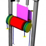
Again, the wire ropes have smoothly become unwound from the remaining outer blocks, keeping the tension on the sandwich constant. Summarizing, the geometry of the pull exerted by the sandwich is always longitudinal to the bridge and tangential to the area being bent (ideally, a line). This is the important difference that sets apart this design from all others based on tensioned slats: the operator will never have to work against the pull from the pneumatic cylinders. With this basic design, some problems can be anticipated. The most difficult to overcome for a small guitar maker is the apparent need of a very sturdy construction, usually associated to bulky metal parts. That problem can be reduced by changing the point where the wire rope is attached to the bridge, as shown here:
That way, the efforts on the bridge will tend to compress the legs, not to join them. Additional control can be gained from modifying the position and length of the wire rope end attachment. Notice that the pneumatic cylinders can be attached to any of four points, achieving the same result. These points are the ends of the slats and the ends of the wire ropes. When attached to the chassis ends of the wire ropes (next figure), the bridge will be lighter and everything will be more compact.
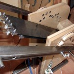
Another way of making the bridge lighter is to use it for bending all the curves except the lower bout. All these improvements over the basic design have been implemented in the machine shown above. Perhaps now you can recognize some of its parts..
